About a year or so ago, a friend of mine tweeted that he’d just taken delivery of an 8-bit computer kit. I was intrigued and immediately started watching Ben Eater’s series of videos on YouTube. I was catapulted back to my Software Engineering days at Imperial College in the 90s. At the time I was only really interested in software, but since watching Adrian Black’s channel I have developed a late interest in electronics.
I ordered the Eater kit from California. It comes in four modules:
- Clock module
- Registers and ALU
- RAM and Program Counter
- Output and control logic
As the kit is built on solder-less breadboards, no soldering iron is required (I did use one to create the data bus LED though, as you’ll see.) The clock module comes with a 5V/2A power supply. The only other tools I used were wire stripper, wire cutter and long-nosed pliers. A multi-meter or logic probe was also useful.
Clock module
The first box contains the parts needed to create the clock, along with a 5V/2A power supply. The clock is comprised of three NE555 ICs configured in Astable (oscillator), Monostable (timer) and Bistable (latch) modes. Essentially, Ben creates a speed-controllable clock (using a potentiometer), with a manual step mode controlled by a switch. The manual step became essential when debugging issues with data movement later.
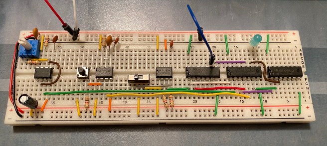
As you can see in the picture, the 555 is use to create the oscillator on the left, a push button is used to step the clock, and the slide-switch in the centre controls which is output (represented by the blue LED.) I only thing that could have been better with this module was to supply red and black wires for +5V and 0V. I also discovered that I needed to use a bigger electrolytic capacitor than provided to prevent the step button bouncing, creating more than one clock pulse per press.
Registers and ALU
The computer consists of two registers, “A” and “B”, in addition to an Arithmetic Logic Unit (ALU). The registers can be loaded from the data bus and then the ALU will automatically add or subtract them using 2’s complement. The output of the ALU can then be output back onto the data bus.

The photo above shows 00011110 – 00000111 = 00010111, or 30 – 7 = 23 in decimal (base 10.) These registers was the first time I had seen a bus transceiver in action (an IC that can be in three states, read, write and disconnected.)
RAM and Program Counter
Next I created a Memory Address Selector (MAS), which consisted of four bits. This is programmed using DIP switches and a read/write switch. In write mode, once the address is selected with the DIP-4 switch, the content of the DIP-8 is written to the RAM. In read mode, the content of RAM is read and displayed.
The Program Counter is one of the most important components of a CPU, as it determines from which memory location the next instruction to be executed should be read, and increments on each clock cycle. This module consists of four bits that count from zero to fifteen, before resetting back to zero, and counting again.
Output and Control Logic
One of the trickiest parts to build, from a wiring perspective, was the decimal output display. This would be able to read a byte and display it as a number. It was hard to get the wires to each of the four segment displays. The way it works is very clever, but I won’t go into it now. Essentially it updates each display sequentially so fast that it appears to be controlling them all at once.
Once all the pieces were in place, it was time to create a control word that would tell each module when to read from and write to the data bus. This is critical to getting the computer to do useful work. The sequence of steps was controlled using microcode stored in EEPROM (Electrically Erasable Programmable Read Only Memory.) As the program counter counts, an instruction is read from RAM via the MAS into the Instruction Register, where it is decoded into a series of microcode steps that drive the control word, making the computer work. Neat.
The Final Result
After many weeks of lockdown with a pair of pliers and wire strippers in my hand, I finally completed my little project. I even mounted it on a piece of wood with labels. It was great fun and I learned a lot. Be prepared to deal with a lot of wire, especially when it comes to the yellow control wires.

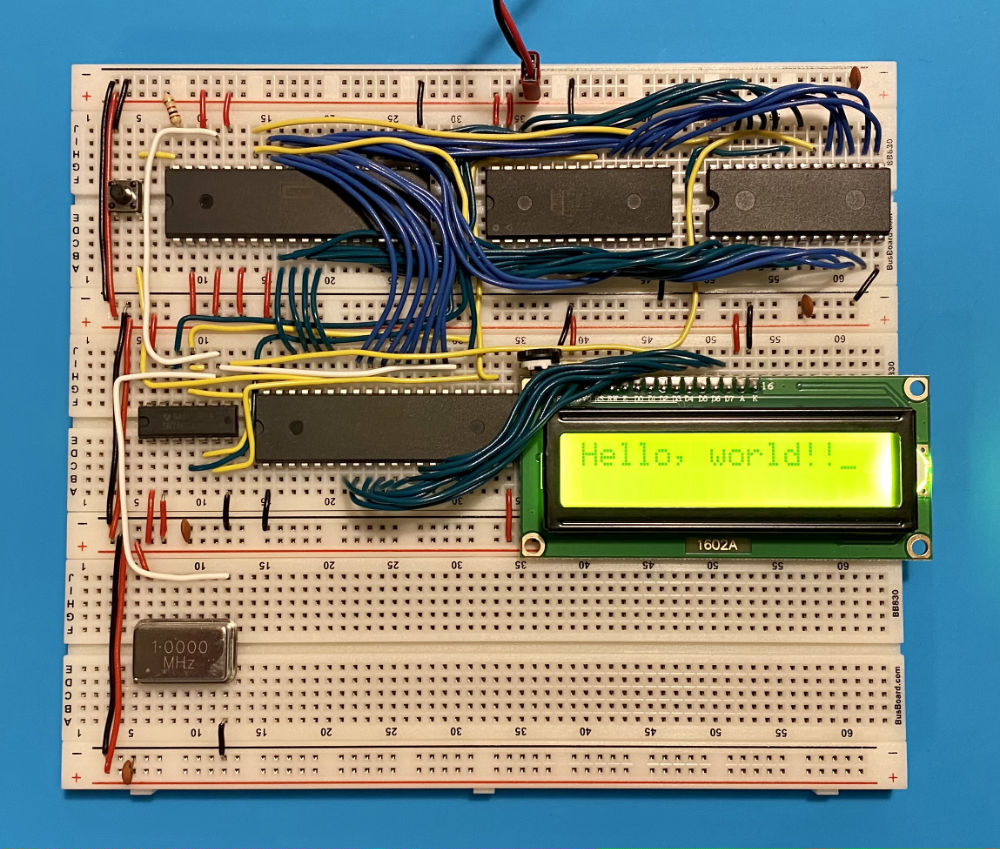
After this project, I bought Ben Eater’s 6502 computer kit and built a working computer, complete with an LCD screen for output. This was driven by a crystal clock and again used EEPROMs for storing the program. In this case I really was building a computer with a 6502 CPU and a 6522 input/output IC. I have since bought a Z80 CPU, but I haven’t had time to build anything with it yet. One day!